BLDG 7604 & 7606 were converted from their current use into Company Operations Facility’s (COF’s).
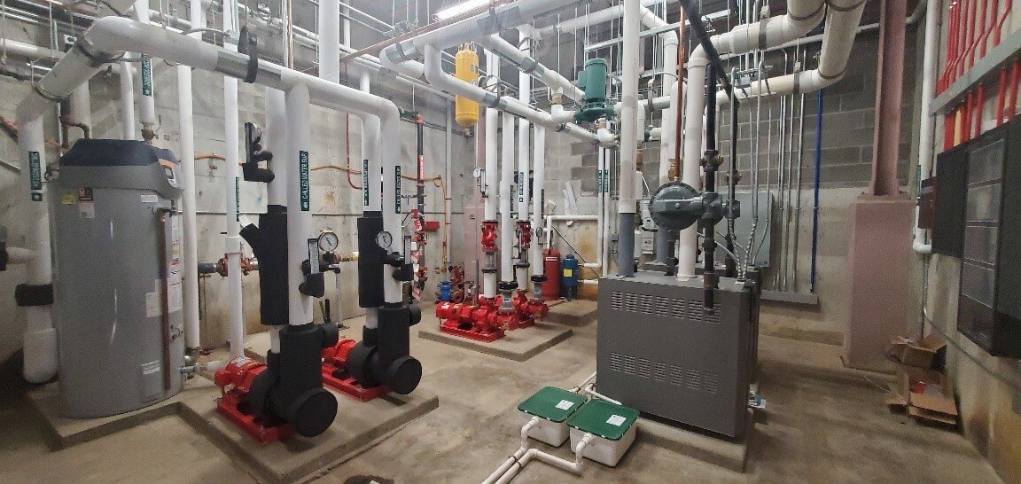
Each building is to be hydronic heated with two condensing type boilers that can operate independently or simultaneously at modulating firing rate to meet the building needs. Boilers have the capability of standalone control or can be commanded by the Building Automation System. Each boiler will have its own primary boiler pump and receive a run command directly from its associated boiler. There will be two building hot water circulating pumps for lead lag operation and to balance operating hours of each. The building circulating pumps will be VFD ready. VFD’s to be provided and controlled by the controls contractor. There will be hot water coils in the two AHU’s to provided necessary heating capacity for the various zones throughout the building. These coils will have modulating two way valves provided by the controls contractor. AHU1 will have a pre-heat coil is the standard position and a re-heat coil downstream to offset the chilling effect during necessary dehumidification of the locker room area. AHU2 will have a pre-heat coil providing heat to the various ducted zones and VAV’s providing final heating to the zoned rooms.
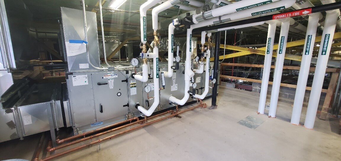
AHU 1 & 2 will have chilled water coils installed and sized for the various loads throughout the building. The coils will have modulating two way valves sized to provide the necessary GPM required for the cooling loads.
AHU1 dedicated to the locker room area will have two heating coils and one cooling coil The first heating coil will provide the primary heating requirements and the second heating coil will provide the re-heat capability for use when the system humidity controls calls for dehumidification. This AHU will have a VFD ready fan motor. The VFD and controls will be provided by the controls contractor. There will be a ducted air distribution system providing conditioned air the locker room area to maintain temperature and humidity control. There will be a powered return air fan providing return air to the AHU and also in conjunction with modulating air dampers allow for relief air into the ventilated attic area. This fan motor will have a VFD ready motor. VFD and controls to be provided by the controls contractor.
AHU2 dedicated to the remaining various areas and controlled by zoning VAV’s. AHU2 will have a primary heating coil with modulating two-way valve serving the ducted distribution system with zoning VAV’s. The VAV’s will have re-heat coils along with two-way modulating valves to maintain zoning temperature control per the controls sequence of operation. It will also have a cooling coil with a two-way modulating valve to maintain discharge air temperature from the AHU. The fan motor will be VFD ready. The VFD and control of it will be by the controls contractor. There will be a powered return air fan providing return air to the AHU and also in conjunction with modulating air dampers allow for relief air into the ventilated attic area. This fan motor will have a VFD ready motor. VFD and controls to be provided by the controls contractor.
Restroom exhaust will have dedicated power exhaust system for both the female and Male restrooms. The sequence of operation and control for these fans will be per the controls contractor.
Equipment and materials provided:
2 – Boilers and primary boiler pumps
2 – Building heating water pumps and associated accessories
2 – AHU’s with heating and cooling coils, VFD ready Motors Filter racks, mixed air chambers with dampers
2 – Return air fans
2 – Chemical feeders
2 – Air separators
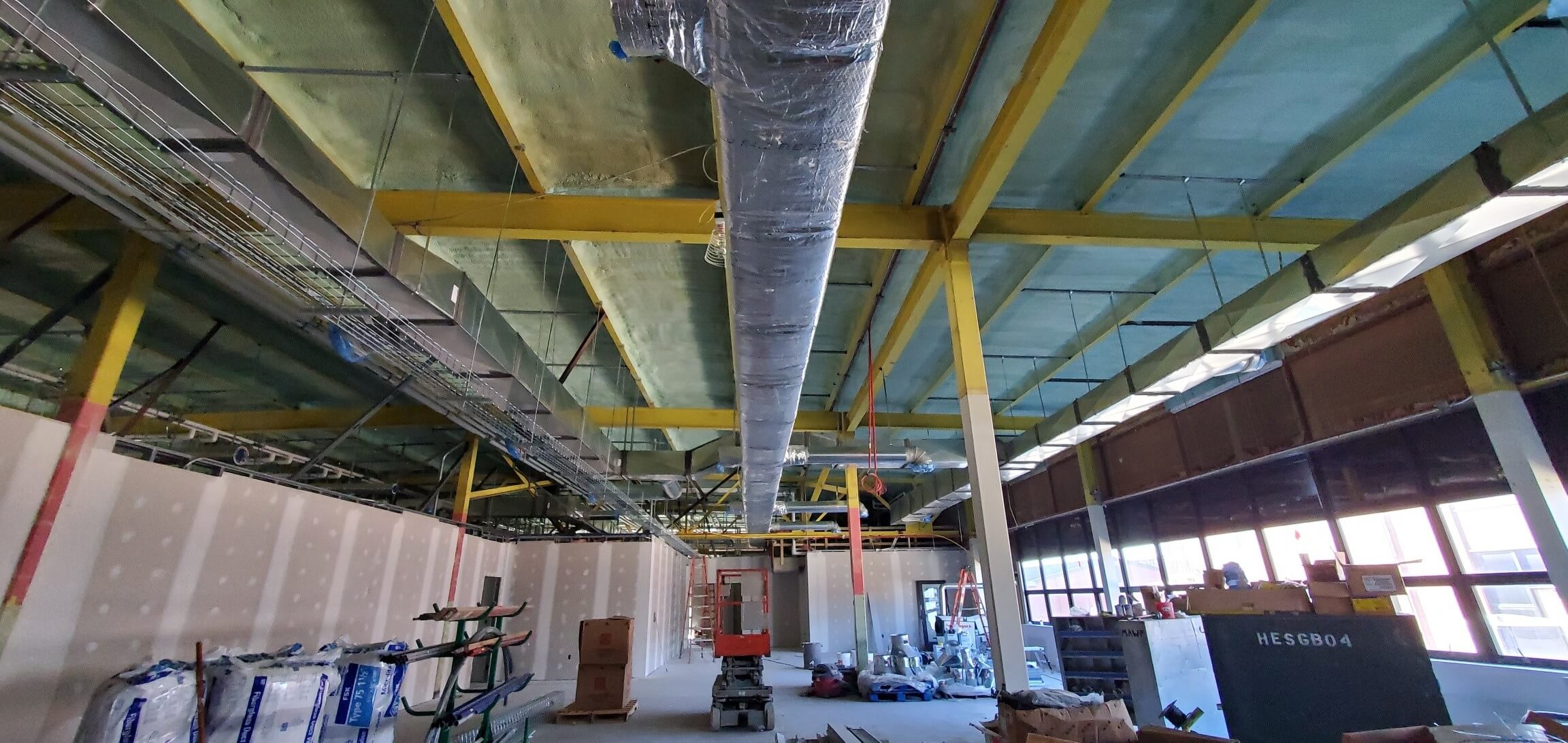
13 – VAV’s
2 – RR exhaust fans. And ducted systems.
1 – Lot of supply air diffusers
1 – Lot of return air grills.
2 – Supply duct systems.
2 – Return air duct systems. With relief dampers for excess air. All associated plumbing fixtures to include lavatories, water closets, urinals. Drinking fountain/bottle filler, janitor sink & faucet.